
- English
- Español
- Português
- русский
- Français
- 日本語
- Deutsch
- tiếng Việt
- Italiano
- Nederlands
- ภาษาไทย
- Polski
- 한국어
- Svenska
- magyar
- Malay
- বাংলা ভাষার
- Dansk
- Suomi
- हिन्दी
- Pilipino
- Türkçe
- Gaeilge
- العربية
- Indonesia
- Norsk
- تمل
- český
- ελληνικά
- український
- Javanese
- فارسی
- தமிழ்
- తెలుగు
- नेपाली
- Burmese
- български
- ລາວ
- Latine
- Қазақша
- Euskal
- Azərbaycan
- Slovenský jazyk
- Македонски
- Lietuvos
- Eesti Keel
- Română
- Slovenski
- मराठी
- Srpski језик

The Use of a Multimeter (2)
2022-03-31
The use of a multimeter (2)
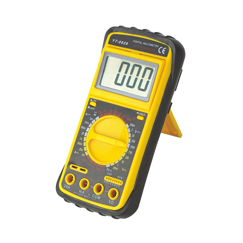
9. The resistance gear can be seen clockwise from the diode gear. There is an Ω symbol, which means the measured resistance gear. When measuring, you should first judge the size of the selected resistance, and then select the knob to select the range. If you do not know the size of the resistance, You can choose an intermediate gear to try to measure, and then change the gear according to the estimated value of the measurement. We use 1K resistance for testing, so change the pointer to 2K gear, and then read the value directly on the display screen. As for the needle part, Since there is no positive or negative resistance, the red and black test pens can be connected to both sides of the resistance (do not touch the test pens when measuring large resistances), regardless of positive and negative.
10. Rotate the knob clockwise to reach the hFE gear. This gear is the gear for measuring the amplification parameters of the triode. Generally, there are two kinds of jacks, one is NPN and the other is PNP. It is clear whether it is an NPN-type transistor or a PNP-type transistor. We use the NPN type here. Since the transistor has three pins, the functions of each pin are also different, so after we distinguish the pins, the correct pin name is used. Inserted into the measuring jack, the magnification of the triode can be directly read out on the display.
11. Rotate the measuring knob again, the next gear is the voltage gear. In this multimeter, both the AC gear and the DC gear are in this range, so before measuring, we should first judge whether the voltage we are measuring is AC or DC, and if you choose the type after confirming If you don't want to measure the type, you can press AC and DC to change the gear, and select the appropriate range. If you don't know what the voltage you want to measure before measuring, you must choose the gear with the largest range. Our common AC is used by families. The AC voltage is 220v, and the typical DC is the output voltage of our computer's USB socket, which is DC 5v.
12. Rotate clockwise, the next step is to measure the frequency. The dial is 10MHz, indicating that the maximum measurement frequency is 10KHz. When measuring, connect the test pen to both ends of the frequency meter, and the measured value can be directly read on the display screen. , The red test lead should be connected to the positive terminal of the signal source correctly, and the negative terminal should be connected to the negative terminal of the signal source.
13. Sometimes a multimeter is used to measure the capacitance. The first step is to determine the size of the capacitance and select the range of the multimeter. After selection, place the test leads on both ends of the capacitor, without dividing the positive and negative poles. If it is a polar capacitance, it can be measured directly without distinguishing the positive and negative poles. Negative, the capacitance at this time can be directly read on the display screen. In addition, it should be noted that when measuring the capacitance, the red test lead needs to be inserted into the jack marked mA, and the result can only be measured on this jack.
Previous:The Use of a Multimeter (1)